Operating principle
Fluorescence microscopy is a type of light microscopy in which an excitation light, here a laser is used, is used to excite fluorescence in the sample. These fluorescent light is then detected. Typically, a fluorophor is mixed with the sample as fluorescent medium. Fluorescence describes the spontaneous emission of a photon after absorption of a higher energy photon. After the atom absorbs a photon, it enters a higher energy vibronic state. Some of the energy is transferred to the surrounding atoms by internal conversion so that the emitted photon has less energy, resulting in a longer wavelength. This wavelength shift is the so-called Stokes shift. In fluorescence microscopy the Stokes-shift is used to separate the beampaths for excitation and detection to prevent the signal from the excitation light. A dichroic mirror is used for this, which is reflective for the excitation light and transmissive for the detection light. Two different approaches of fluorescence microscopy are described in the following. These methods differ mainly in stimulation of the fluorescence and consequently in the signal detection.
TIRFM
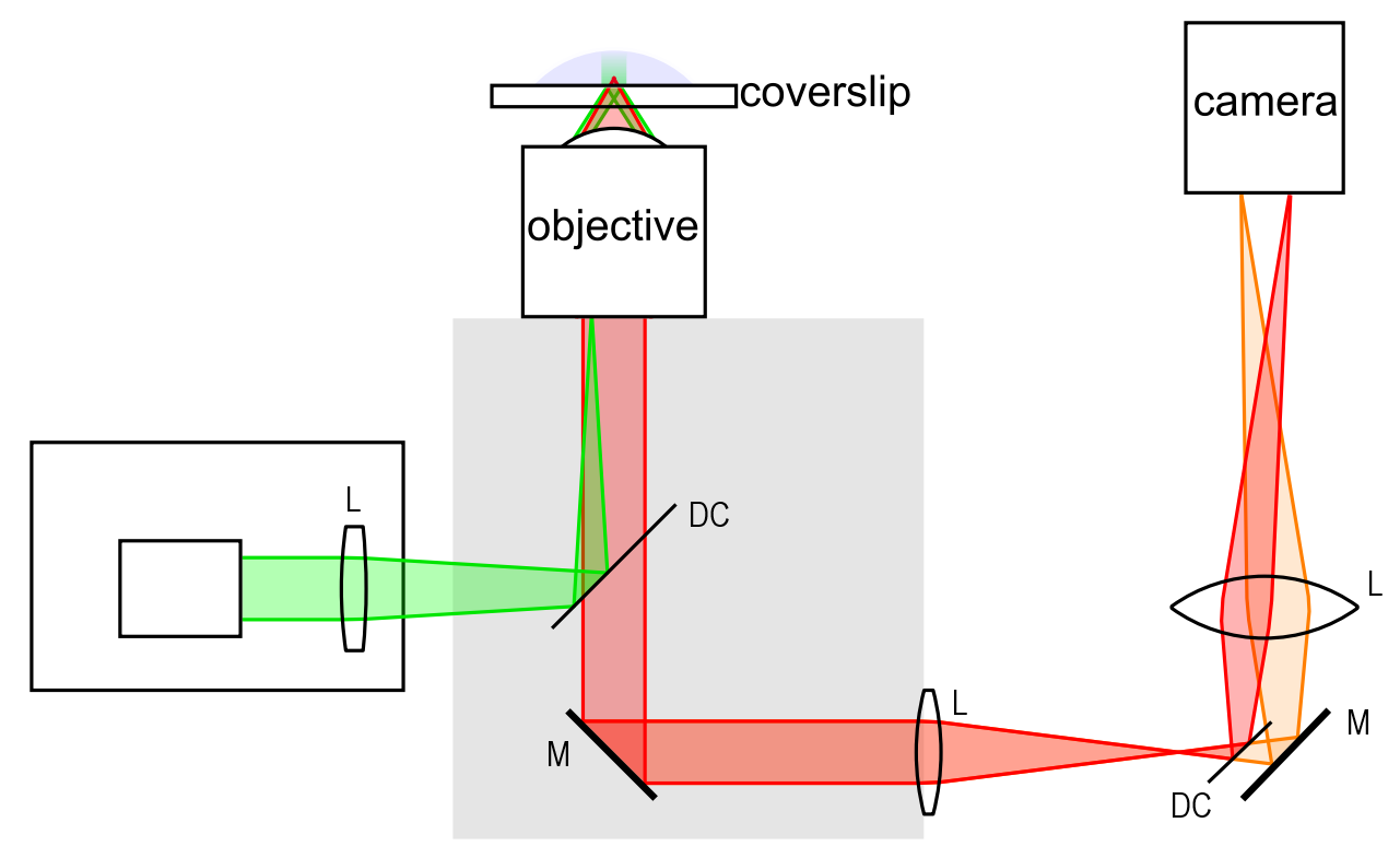
In total internal reflection fluorescence microscopy the fluorescence is stimulated by the evanescent field of the reflected beam. The excitation beam is focused on the border area of the aperture in the back focal plane of the objecitve, so the beam propagates as small parrallel beam behind the objective. The focussing on the border area effects in a propagation under an angle. This is the critical angle for total internal reflection so the beam is reflected at the surface between coverslip and sample. The evanescent field intruding in the sample now can stimulate the sample molecules to fluorescence. Then the signal is imaged onto a camera using lenses. A second dichroic mirror can separate two signals from each other, which is particularliy useful for fret applications.The fluorescence light is collected by the objective, and separated with an dichroic mirror. This is possible due to the stokes shift between the absorbed and emitted light. Because the evanescent field has just a penetration depth of a few hundred nanometer once can just analize the molecules next to the surface. This property together with the small illuminated area and the use of highly diluted samples are the main reason for the ability of single molecule microscopy.
Confocal microscopy
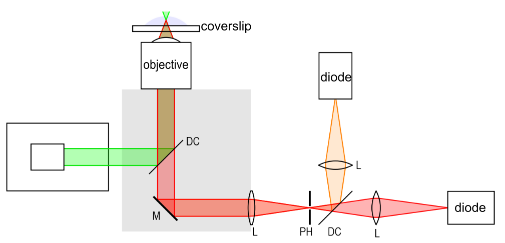
For confocal measurements the excitation beam gets focused inside the sample, so the fluorophor gets excitated in a larger area to emit light. This light gets collected via the objective and imaged on a diode after passing a telecentric lens system. A telecentric lens system consists of two lenses (L) and a pinhole (PH) located in the common focal plane of both lenses to separate the light emitted inside of the focal area and the light emitted outside of the focal area.
This kind of microscopy detects just one signal from a small area in time. Thus, for an image of the entire sample, several measurements have to be taken and merged.
However, it is possible to generate images of the interior of the specimen, whereas tirfm only images the boundary region near the cover glass.
Because only the area within the focal range is investigated, single-molecule investigations are also possible here when using diluted samples.
As with tirfm, a dichroic mirror in the detection beam path can be used to measure two signals separately.
The combined microscope
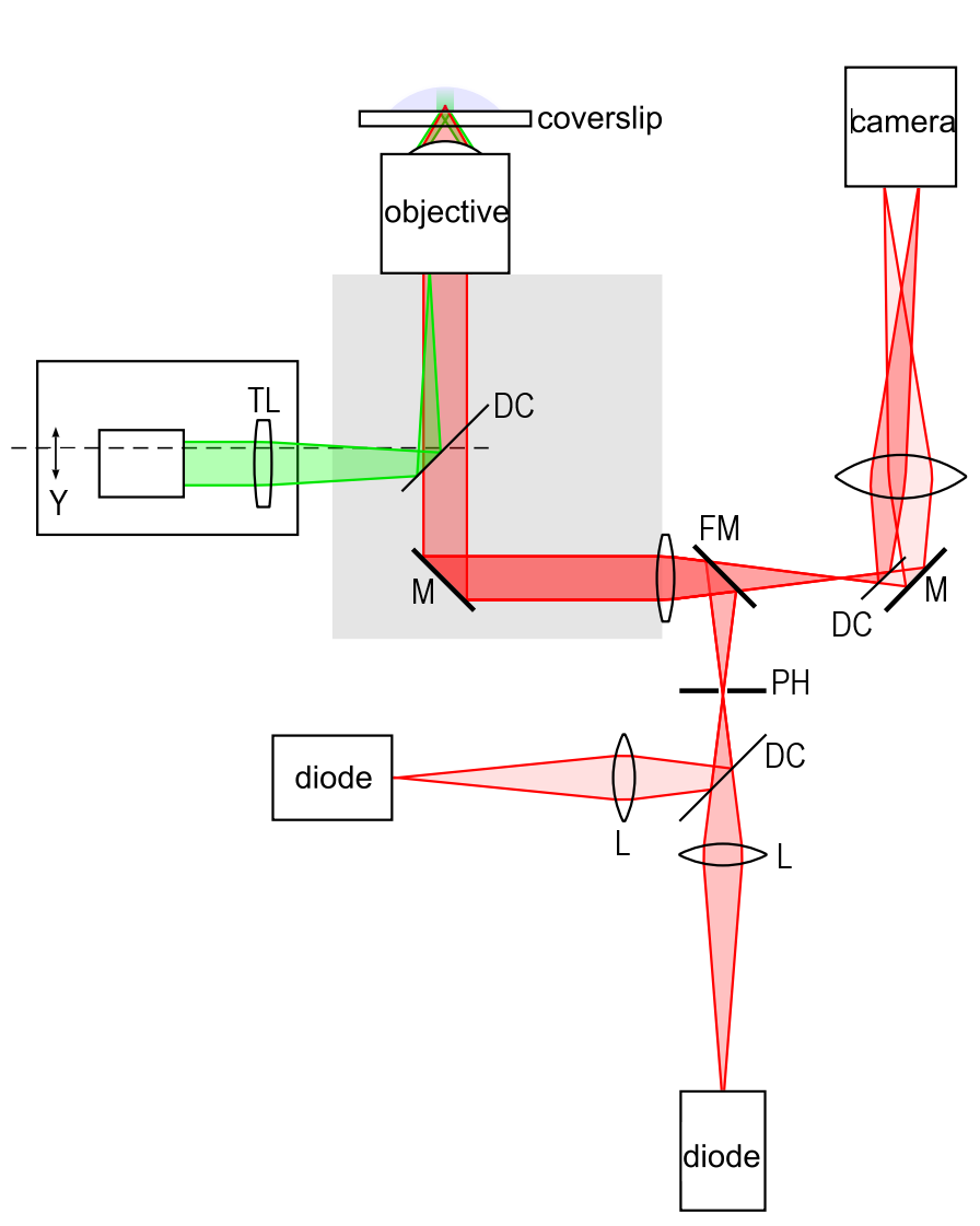
The presented microscopy methods differ mainly their detection beam paths and the way to excitate the sample. But with just a few modifications, it is possible to combine both setups. By positioning the excitation path on a translation stage once can shift the laser in horizontal direction. Furthermore, the tirf lens (TL) is removeable. That allows for switching between tirf and confocal microscopy with just two handles.
A flipping mirror (FM) located behind the tube lens makes it easy to switch between both detection paths so both can remain. A sketch of the beampath is shown in figure 3.